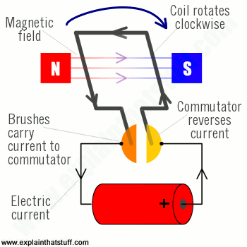
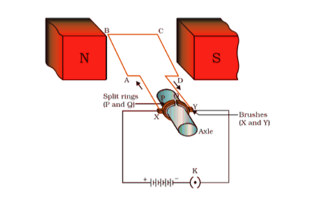
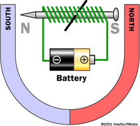
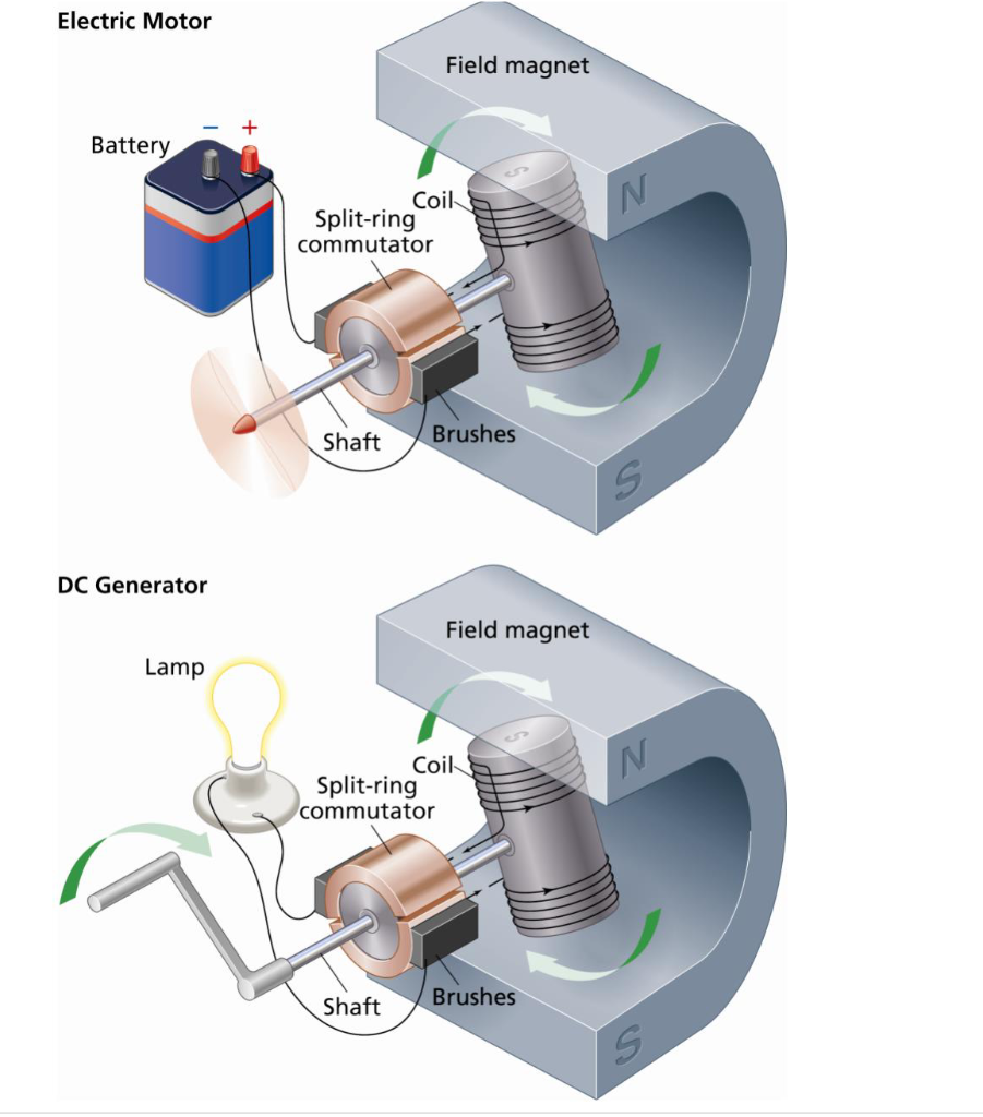
40 electric motor diagram with labels
Electric Motors Symbols - AC/DC, Single Phase / Three Phase Motors This symbol represents a single phase AC synchronous motor. Synchronous motors initially starts as an induction motor but later achieves a synchronous speed which only depends on the input supply frequency. DC Compound Excitation Motor. Such type of DC motor has both the series field winding and shunt (or parallel) field winding. › wiring-diagramEverything You Need to Know About Wiring Diagram - SmartDraw Unlike a pictorial diagram, a wiring diagram uses abstract or simplified shapes and lines to show components. Pictorial diagrams are often photos with labels or highly-detailed drawings of the physical components. Standard Wiring Diagram Symbols. Most symbols used on a wiring diagram look like abstract versions of the real objects they represent.
Electric Motor - Principle, Working, Diagram - Explained step by step View Answer NCERT Question 6 (a) - State whether the following statements are true or false. (a) An electric motor converts mechanical energy into electrical energy. View Answer NCERT Question 11 - Draw a labelled diagram of an electric motor. Explain its principle and working.

Electric motor diagram with labels
Electric Motor Diagrams - Mr. Electrician's Home Page A Repulsion Electric Motor is by definition a single phase motor which has a stator winding arranged for connection to the source of power and a rotor winding connected to a commutator. Brushes and commutators are short-circuited and are placed so that the magnetic axis of the rotor winding is inclined to the magnetic axis of the stator winding. Motor Connection Diagrams - Electric Motor Warehouse Single Phase Terminal Markings Identified By Color: (NEMA Standards) 1-Blue 5-Black P1-No color assigned. 2-White 6-No color assigned P2-Brown. 3-Orange 7-No color assigned. 4-Yellow 8-Red. Three Phase Connections: Part Winding Start: 6 Leads NEMA Nomenclature: WYE or Delta Connected. Basic wiring for motor control - Technical data guide | EEP Wiring diagrams show the connections to the controller. Wiring diagrams, sometimes called " main " or " construction " diagrams, show the actual connection points for the wires to the components and terminals of the controller. Basic wiring for motor control - Technical data. They show the relative location of the components.
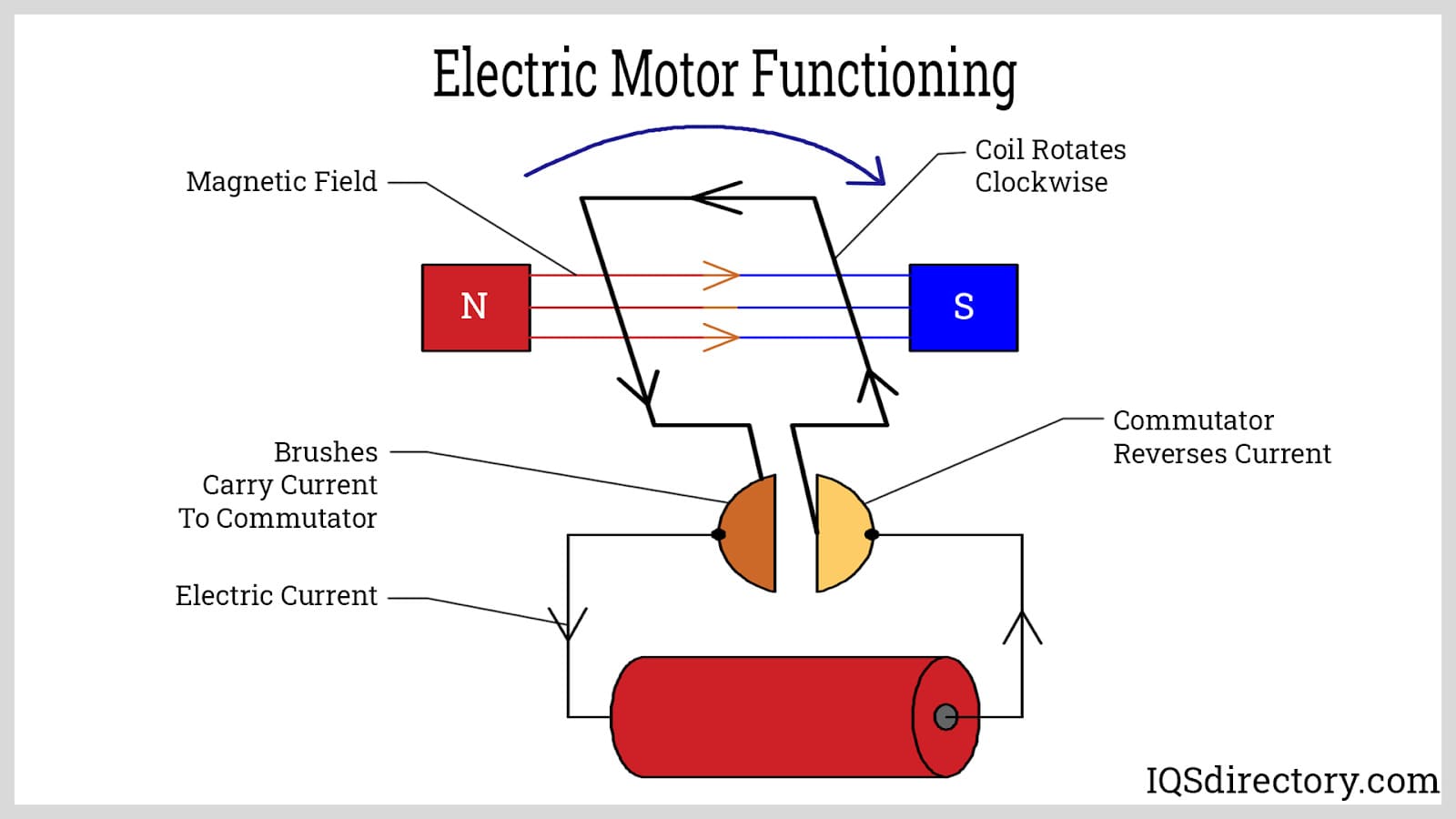
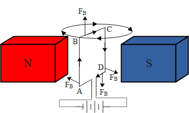
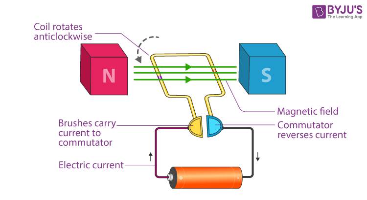
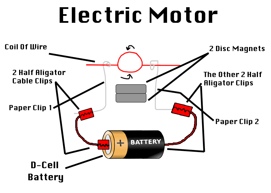
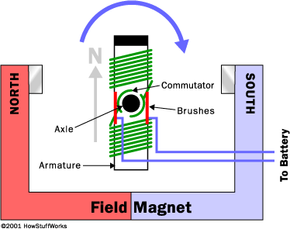
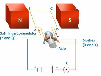
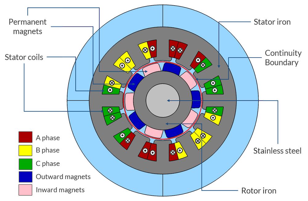
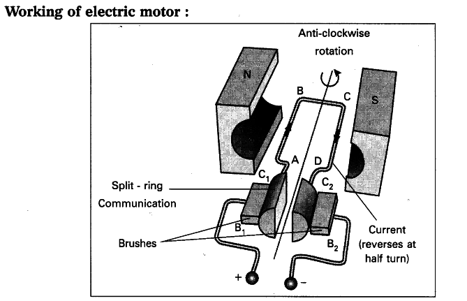
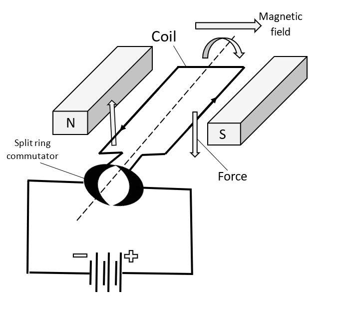
Electric motor diagram with labels. 7 Parts Of Simple Electric Motor And Function - AutoExpose Drive Pulley. 7. Motor Housing. Simple Motor Parts and their function. 1. Stator / Armature Coil. The stator includes the main components of the electric motor. Because this component will be in direct contact with the performance of the motor. The stator is a static copper winding located around the main axis. Draw a labeled diagram of an electric motor. Explain its principle and ... Working of electric motor: As shown in the diagram, when a current is passed through the coil PQRS the coil starts rotating anti clockwise because a downward force acts on length PQ and at the same time an upward force acts on RS. Therefore, the coil rotates in anti clockwise direction. electric motor diagram labeled electric motor diagram labeled Diagram ladder electrical line drawings read drawing single diagrams wiring interpret layout three knowhow. Generator dc construction machine motor alternator ac working function difference between parts yoke field magnetic does works each conductor pole. Electric Motor - Parts of Motor, Working of Electric Motor & Uses - BYJUS Take two bar magnets and keep the poles facing each other with a small space in between. Now, take a small length of a conducting wire and make a loop. Keep this loop in between the space between the magnets such that it is still within the sphere of influence of the magnets. Now for the last bit. Connect the ends of the loop to battery terminals.
Electrical Symbols, Electrical Diagram Symbols - ConceptDraw Electrical rotating machines, such as motors and generators, are vital assets for any power plant or large industrial company. An electric motor is an electrical machine that converts electrical energy into mechanical energy. The reverse of this would be the conversion of mechanical energy into electrical energy and is done by an electric generator. In normal motoring mode, most ... 3 draw a labeled diagram of an electric motor explain Ans : Electric motor labeled diagram of an electric motor is as follows : Principle : the electric motor is a rotating device that can convert electrical energy into mechanical energy . An electric motor is based on the principle that the current - carrying conductor experiences a force when placed in a magnetic field . The direction of the ... Single Phase Electric Motor Wiring Tutorial: Baldor, WEG, Leeson In this video, Jamie shows you how to read a wiring diagram and the basics of hooking up an electric air compressor motor. These tips can be used on most electric motor brands such as WEG, Baldor,... › us › enDelta® Ultra- Light 1000, Semi-Electric Bed - Drive Medical The motor is UL approved ; In the event of a power failure, a 9 volt battery, located in the motor, can lower the head and foot sections nine times ; No crank needed ; New and improved hand pendant has large, easy-to-use controls (Figure E) Bed ships in two cartons ; Channel frame construction provides superior strength and reduced weight
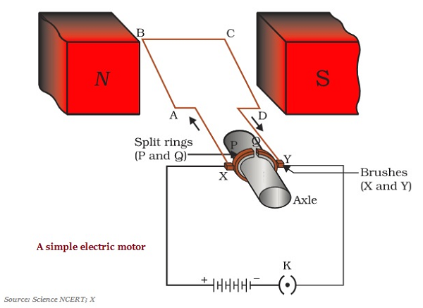
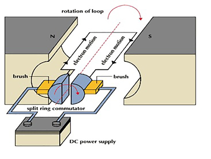
Draw a labelled circuit diagram of a simple electric motor and explain ... The main parts of electric motor are the magnets, armature, split ring commutators and brushes. The armature consists of a rectangular coil made of insulated copper wire wound on a soft iron core. The coil is mounted on an axle and is placed between the cylindrical concave poles of a magnet. Electric motor Diagram | Quizlet attract and repel other magnets, attract only magnetic material. electric motor. an electrical machine that converts electrical energy into mechanical energy. generator. a device that converts motive power (mechanical energy) into electrical power. magnetic levitation. method by which an object is suspended with no support other than magnetic ... Electric Car Diagram | Car Construction Car Anatomy and Repair, Electric car, Engine, How a car Works, Construction. The active reference to source is obligatory if you use materials of a site Car Anatomy 1004 shares How to Read an Industrial Pump Motor Wiring Diagram Each motor has several wires in it which are labeled with letters and numbers. For "Line", take the wires the diagram instructs, wrap them together, and connect them to the incoming voltage. For "INSUL", take the wires, wrap them together, and twist them into an insulated cap. Once this is done, the motor is ready to be turned on.
Electric Motor Nameplate Details Explained | Electric Motor ... The nameplate shown in Figure 1 indicates the electric motor is rated 1 HP. With a service factor of 1.15, the motor can be overloaded up to 1.15 horsepower. If the motor is operated in the service factor range continuously, it will cause a reduction in motor speed and efficiency, and an increase in the motor's operating temperature.
› worksheets › ac-motorAC Motor Control Circuits Worksheet - AC Electric Circuits After the motor has had time to speed up, another set of “starter” contacts bypass line power around the resistors, directly to the motor windings. Draw a diagram showing how this could be done for a single-phase electric motor, using two starter contacts: “R” for “run” and “S” for “start”.
Draw a labeled diagram of an electric motor. Explain its principle and ... Draw a labeled diagram of an electric motor. Explain its principle and working. What is the function of a split ring in an electric motor? Solution Principle: It works on the principle of the magnetic effect of current. A current-carrying coil rotates in a magnetic field.
fueleconomy.gov › feg › atv-evWhere the Energy Goes: Electric Cars - Fuel Economy Electric cars use regenerative braking to recover energy typically wasted in braking. When you apply the brakes, the vehicle's inertia turns an electric motor-generator, producing electricity that is then stored in a battery. The electricity can later be used to power the electric motor, which supplies power to the wheels.
Electric Motor Diagram Illustrations, Royalty-Free Vector Graphics ... Browse 983 electric motor diagram stock illustrations and vector graphics available royalty-free, or start a new search to explore more great stock images and vector art. Newest results Direct current generator Generator info graphic for science education. Illustration. Engineering backgrounds. Mechanical engineering drawing
Draw a labelled diagram of an electric motor. Explain its ... - Sarthaks Working of Electric Motor Current in the coil ABCD enters from the source battery through conducting brush X and flows back to the battery through brush Y. The current in arm AB of the coil flows from A to B. In arm CD it flows from C to D, that is, opposite to the direction of current through arm AB.
Motor Connection Diagrams (OLD LECTURE) - YouTube Please use the updated lecture at:
labeled diagram of electric motor labeled diagram of electric motor Need Help with bench top milling machine with 110/220 wiring. 8 Pictures about Need Help with bench top milling machine with 110/220 wiring : Simple Electric Motor Vector Diagram Stock Vector Art & More Images of, Working or Operating Principle of DC Motor and also .
Electrical Diagrams and Schematics - Inst Tools Types of Electrical Diagrams or Schematics There are three ways to show electrical circuits. They are wiring, schematic, and pictorial diagrams. The two most commonly used are the wiring diagram and the schematic diagram. The uses of these two types of diagrams are compared in Table 1.
› wiring-diagramWiring Diagram – A Comprehensive Guide | EdrawMax Online A wiring diagram is a visual representation of components and wires related to an electrical connection. This pictorial diagram shows us the physical links that are far easy to understand an electrical circuit or system. One wiring diagram can signify all the interconnections, thereby signaling the relative locations. The use of a wiring ...
What is an Electric Motor? with the Help of a Labelled Diagram ... An electric motor is a device that converts electrical energy into mechanical energy. Diagram: Electric motor Working of an electric motor: An electric motor works on the principle of magnetic effect of electric current.
Basic wiring for motor control - Technical data guide | EEP Wiring diagrams show the connections to the controller. Wiring diagrams, sometimes called " main " or " construction " diagrams, show the actual connection points for the wires to the components and terminals of the controller. Basic wiring for motor control - Technical data. They show the relative location of the components.
Motor Connection Diagrams - Electric Motor Warehouse Single Phase Terminal Markings Identified By Color: (NEMA Standards) 1-Blue 5-Black P1-No color assigned. 2-White 6-No color assigned P2-Brown. 3-Orange 7-No color assigned. 4-Yellow 8-Red. Three Phase Connections: Part Winding Start: 6 Leads NEMA Nomenclature: WYE or Delta Connected.
Electric Motor Diagrams - Mr. Electrician's Home Page A Repulsion Electric Motor is by definition a single phase motor which has a stator winding arranged for connection to the source of power and a rotor winding connected to a commutator. Brushes and commutators are short-circuited and are placed so that the magnetic axis of the rotor winding is inclined to the magnetic axis of the stator winding.

![Expert Verified] draw a labelled diagram of an electric motor ...](https://hi-static.z-dn.net/files/dab/56da13db27ea5b6a3128c7861117c25a.jpg)















Post a Comment for "40 electric motor diagram with labels"